


Direct MP3 Download: The Makerz #22 – I Blame Chad
TheMakerz – #022
iTunes: https://itunes.apple.com/us/podcast/themakerz-podnutz/id1242688847?mt=2#
RSS: http://feeds.feedburner.com/themakerz
Patreon: https://www.patreon.com/themakerz
Show – http://podnutz.com/category/themakerz/
Live Video And Chat – https://www.patreon.com/themakerz
Email – themakerz@podnutz.com
Hosts:
DoorToDoorGeek – Steve McLaughlin – http://Podnutz.com
Jonas Rullo aka Bambiker, aka jrullo on IRC Tumblr: http://bambiker.tumblr.com/
Chad Cory – youtube – watchmydiy https://www.youtube.com/channel/UCnXEH0eHynU464l5Lw9zyEw etsy shop – c3dbycac https://www.etsy.com/shop/c3dbycac
Brett Hansen – @Newstalgic Twitter
Aaron Turnbull – aar510430@gmail.com
flyingRich – http://flyingRich.com
Liam Tidwell – LiamTek.com https://www.etsy.com/shop/3DTek
James – james@cad9.design
Contact:
Email – themakerz@podnutz.com
Instagram – http://instagram.com/themakerzpodnutz/
MeWe – https://mewe.com/group/5884ebf15b25bc52222e1ffc
YouTube – https://www.youtube.com/channel/UC254waH49Ar28JfPvVnhw-A
**************************************************************************************
Eric –
DoorToDoorGeek –
ERRF 2018 | East Coast RepRap Festival
The East Coast RepRap Festival (ERRF) invites all community members connected to 3D printing to join us and celebrate the diversity throughout our community and industry. We are inviting companies and individuals to bring out their 3D printers and projects big & small.
http://eastcoastreprapfestival.com/
Make 3D-Modeling Child’s Play with a Can of Play-Doh
You need to replicate a small part on a 3-D printer, so you start getting your tools together. Calipers, rulers, and a sketch pad at a minimum, and if you’re extra fancy, maybe you pull out a 3D-scanner to make the job really easy. But would you raid your kid’s stash of Play-Doh too?
https://hackaday.com/2018/05/04/make-3d-modeling-childs-play-with-a-can-of-play-doh/
Nintendo Labo Piano Cards by theinventineer
If you print this Thing and display it in public proudly give attribution by printing and displaying this tag.
https://www.thingiverse.com/thing:2889822
Chad Cory –
LightBurn is layout, editing, and control software for your laser cutter. With LightBurn you can: https://lightburnsoftware.com
Cohesoion3D: Powerful Motion Control: http://cohesion3d.com
Jonas Rullo –
Back to basics 3D modeling for the Fusion 360 shy. Using Inkscape and Tinkercad.com to model real world 3D parts. This video shows how to make a quadcopter motor mount based on a part in hand.
https://www.youtube.com/watch?v=vrU2eZ6URd8&t=9s
Without having to learn the ins and outs of real CAD programs, you can create your own models using layers in Inkscape. Diy3dtech.com has several good beginner, howto, and why do it this way this type videos for 3D printing, laser cutting and CNC. Diy3dtech.com @ Thingiverse
Manual Z-axis bed for K40 or any laser system. https://www.youtube.com/watch?v=oGdAx8lk1qg&t=280s
3D print a snap on sacrificial base to sit on top of the platform lift. Shows a design with pegs and magnets to hold the part slightly above the bed base so the part doesn’t fall to the bottom of the machine and getting recut by the lasers subsequent passes. Once your bed gets zapped too many times, just print another.
Add an ESP8266 to any RAMPS style 3D printer controller. https://github.com/luc-github/ESP3D/wiki/Install-Instructions
Liam linked to one of Chris’s videos, this is another.
This is interesting because you can plug this module onto the printer controller and give it it’s own web page. Similar to Raspberry Pi with Octoprint but it runs on the printer itself. You send the gcode to the printer, just like it was on it’s own SD card. If the wifi signal is lost, it doesn’t matter because the gcode runs from the attached module. Once a print starts you would only need wifi access if you wanted to control the printer remotely.
- Now full support of Marlin / Marlinkimbra / Repetier / Smoothieware
From the department of, You’re Doing It Wrong: Relativity wants to do it right by 3D printing rockets with 1000 times fewer parts than usual.
“Relativity is deep into development of its Aeon 1 rocket engine, which uses a mixture of oxygen and methane fuels. The Aeon engine has a modest vacuum thrust of about 19,500 pounds, less than one-tenth that of a Merlin 1D engine used in SpaceX’s Falcon 9 rocket. It’s also nearly four times more powerful than the small Rutherford engines that power Rocket Lab’s smaller Electron rocket.”
“The company has a clear long-range vision that, ultimately, all rockets will be 3D printed because the highest cost today is human labor. “We really feel like that, extrapolating into the future, if we could 3D print 90 to 95 percent of the components of a rocket, we will have a launch vehicle that would be very disruptive,” Ellis said. “Fundamentally, this is the cheapest possible rocket.”
https://arstechnica.com/science/2018/03/relativity-space-reveals-its-ambitions-with-big-nasa-deal/
Billion dollar companies like Boeing and others are 3D printing big and/or complex parts that could not be manufactured otherwise. https://www.theverge.com/2017/4/11/15256008/3d-printed-titanium-parts-boeing-dreamliner-787
Like Titanium? Check this: http://www.norsktitanium.com/technology
They’re making printers that print with Titanium wire, AKA filament. From the pictures, it looks like they rough print the parts and machine them to the final shape. Really awesome looking Ti metal work.
BLTouch (auto bed leveling; really tramming) for the original CR10 (not the new board with filament sensor and double Z axis)
If you like the glass bed of the CR10 and want bed tramming, a regular inductive sensor isn’t going to work. Capacitive sensors give false positives in all kinds of conditions. BLTouch still isn’t the best, but unless you can do inductive sensing, touch sensing is where it’s at. Great sensor test video here: Tom Sanlanderer
BLTouch is a particular kind of Z end stop sensor. It’s a servo with a sensor pin. There is an electromagnet in the top of the sensor with a pin in the center. It’s very much like a solenoid on machinery or car starter, but not really. It’s the same but opposite. When a slight pressure moves the pin, the electromagnetically suspended pin moves a tiny amount which changes the voltage in the coil which is sensed by the servo and sends a signal to Marlin thus sensing the location of the hot end in the Z axis.
Connecting this to the original CR10 is a little trickier than most any other board. Here’s a pretty good tutorial complete with firmware for Marlin 1.1.6.
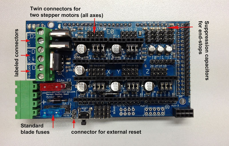
Essentially, the manufacturer did not provide/expose unused/extra pins of the Atmel microcontroller. Other manufacturers have at least a few if not many extra pins sticking off the main board unused. Just have a look at any RAMPS board and you’ll know what I mean.
http://reprap.org/mediawiki/images/thumb/8/81/RAMPS_1.4.2.jpg/800px-RAMPS_1.4.2.jpg
CR10 is not so generous.
I did find an adapter board on ebay that does what I describe below without cutting wires and soldering. The no solder connector board from ebay.
- The original CR10 does not have a bootloader. You will not be able to write the Marlin firmware without first adding a bootloader to the microprocessor board. The bootloader allows you to put the main board into programming mode so you can add Marlin firmware to your machine. Unless you bought a CR10 form Tiny Machines, you’ll need to do this yourself. Follow this well known tutorial to burn your bootloader if you haven’t already. Once you do this, you can write the Marlin firmware via the USB cable.
- We need a signal line of some kind for the sensor. Not great news on the CR10 original: Unless you have a microscope and can solder to ultra tiny pins on the surface mounted microcontroller, you’re going to need to disable at least one stock feature. You have to disable one stock feature for each new feature you want to add to this model of the printer. Most are choosing either the Beep signal line, or the SDcard signal line. Here, we’re disabling the Beep function of the display and using that as the signal for the BLTouch servo. The servo is the electromagnet system that moves the tip of the BLTouch sensor up and down. We’ll cut the brown line on the LCD display (the buzzer signal) and use that as the sensor signal. Wire cut here. Connector was here. We’ll also have to set the “Pin 27” to be used as a Servo in Marlin firmware so that the software will use the sensor signal for the auto leveling. The no solder connector from ebay.
- The BLTouch also needs 5V power to run. If you recall, the hot end fans have 12V power, which isn’t going to help us. (if you really wanted to, you could wire up a mini buck converter to step down the always on hotend fan and save running 2 of the wires). There are a couple ways to get 5V. The easiest way is to use the voltage lines on the ICSP(In Circuit Serial Programming connector) connector. You would have used this to burn the bootloader onto the main board. Follow this well known tutorial to burn your bootloader if you haven’t already. The top and bottom of the ICSP connector has the required voltage without soldering extra wires. From the tutorial above. Just connect using the push pin connectors included with the BLTouch kit. (BLTouch could also use 3.3V, however you would need to cut a trace on the back of the sensor, under the plug connector; and find a 3.3V supply)
- Next we need to replace the existing Z-axis end stop main board connector with the BLTouch Z connector. It’s the black and white wire connector from the BLTouch. Extend as necessary from the hot end mount. Black is ground and White is ZMIN (minimum position of the Z axis end stop, CR10 only has one end stop per axis, ZMAX would be at the top of the machine if there was one). Plug in the Z-stop of the BLTouch into where the original CR10 Z-stop was(on the main board). If you have a JST type connector, you could unplug the old switch end stop on the frame and connect to the BLTouch. This would only save you having to snake the Z-stop into the box with the sensor wires.
- Find a mount. Here’s one for the original hotend: Original CR10 hotend mount. E3D has a lot of V6 upgrade prints on Thingiverse here. My V6 hot end mount was none of these. I was able to combine one of the parts from the hot end mount I have with a BLTouch connector pattern from here into one part. Tinkercad imports .STL files pretty well for this kind modification.
- Extend the wires from the BLTouch into the main case and connect. Some kits include long wires, I just used an old ethernet cable. The BLTouch kit has several push pin connectors for making the connections. Orange goes to the pin 27 of the ribbon cable cut earlier. Brown to ground on the ICSP. Red is 5V on ICSP.
- Update your firmware to enable the auto bed leveling(actually tramming). If you haven’t burned a boot loader to your machine, you’ll need to follow this before you can give it a new Marlin firmware. I tried just using the github version and applying the modifications, but it was too large. After compiling, the stock firmware with BLTouch enabled would not copy over. This one has more than the standard modifications and fits on the machine with a little space left over. a Marlin 1.1.6 CR10 firmware with BLTouch enabled using pin 27. All the software is taken care of for you. The only thing to change is the location of where your BLTouch is mounted in relation to the hot end. Notes from the manufacturer, BLTouch are here: https://www.antclabs.com/manual. Tom Sanlanderer has a good video on setting the offsets for the location of the sensor. See minute 6:50.
- After everything is wired up, turn the machine on. The pin of the sensor should drop down and retract twice. This is a self test when powered on. It does not mean that your machine is communicating with the sensor. If both the blue and orange LED are on and the pin is up, then you have a good servo connection to the main board. You should be good to close everything up and begin leveling. If you don’t see both LEDs on, then you need to check all your connections are solid before continuing.
- Set the Z offset. The firmware is set to zero Z offset by default. BLTouch suggests setting it to 2 which is supposed to be 2mm above the bed. You can reflash your firmware with the change if you want, I left it as is. First run the Auto Home from the printer control panel. If you don’t see the pin stick in the down position with the orange LED off, stop and check your connections. If the pin is not down, the Z position will not be detected and the hot end will drive into the bed. Always be prepared to hit the power until you get this working perfectly. Back to the paper test. Get a sheet of paper and go to the Prepare->Move axis->Move Z. Adjust Z toward the bed until the paper is just sliding against the hot end. Remember that number and then set that number on the Control->Motion->Z Offset menu option. Save settings on the Control->Save Settings option.
- Auto Home again, then run Prepare-> Bed Leveling to set the final 9 point mesh tramming program. You only step 9 and 10 if your first layer is not what you want, or if you change your bed leveling wheel adjustments.
I didn’t have to add any special Gcode to my printing routines since updating to Marlin, also defaults to enabling the EPROM save settings option. After you’ve saved your Z settings, the next time you use your printer, you don’t have to set everything up again.
The results are not staggering, but the couple of tests I ran that spanned the bed all stuck to the first layer. I can still see varying squish of the first layer when comparing prints on the left, center and right. Samples here
The center layer lines are less close together compared to the left and the right. The left and right are just about the same. The pieces in the photos are arranged as they were on the bed, except the actual print was far left, center and far right. I moved them closer together in the picture to get them in the same frame.
Interesting things I found about the Servo settings of Marlin/Gcode. M280 Servo Position Gcode
M280 syntax: M280 PX SXXX
Where P10 is the servo number and S10 is the degree position to set.
The servo mode of a pin does take commands as though you were using a traditional RC servo. A servo always has a square wave signal sent to it from the moment its powered on. The angle that the servo turns is controlled by changing the pulse width of the square wave signal.
M280 P0 S10 is a typical command (sets the pin to deployed on the BLTouch). P0 is the zeroith servo that you’re sending the command to. SXXX is the value your sending. S10 is ten degrees. S60 is 60 degrees, etc. Any S value above 200 is the direct pulse with of the signal in microseconds.
At first I wasn’t sure that my printer was set to use the servo mode in the firmware correctly. My BLTouch only ran it’s power on self test and didn’t respond to any commands. I went through checking my connections several times and still nothing. At that point I hooked up my Bitscope oscilloscope to see if the pin was actually set to servo mode. I found that there was a good signal coming from my control board. After more checking and wire re-crimping, my BLTouch finally had a blue light and then it responded to commands.
On an oscilloscope, you can see the square wave pulses widen when you issue M280 commands. This is how I verified that the printer was interpreting the commands properly. When I sent Gcode via the Octoprint Terminal tab, I could see the pulse width change. The BLTouch interprets these pulse widths as pin up, and pin down commands. Good connections are of course required. When the pin is triggered, it pops up and sets the ZMIN of the end stop connector and the printer stops moving toward the bed.
Overall the BLTouch is a good sensor for glass. According to Tom’s tests, inductive is far superior if you can use a metal bed. As the glass changes over time, or if you’re unfortunate enough to receive a warped glass from a manufacturer, I expect it will be much more convenient than twisting knobs all the time.
Take pictures with your phone to duplicate 3D objects. It’s tricky but looks like it works with a lot of objects:
https://www.youtube.com/watch?v=ye-C-OOFsX8
James –
Brett Hansen –
Liam Tidwell –
https://youtu.be/H6A1VB99eRo DIY notebooks
https://youtu.be/1FqMyivyOTI Chris’s basement – You have a built printer now what?
Octoprint plugins – part the second
https://github.com/BillyBlaze/OctoPrint-FullScreen/archive/master.zip
https://github.com/dattas/OctoPrint-DetailedProgress/archive/master.zip
https://github.com/cesarvandevelde/OctoPrint-M73Progress/archive/master.zip
https://github.com/foosel/OctoPrint-DisplayZ/archive/master.zip
https://github.com/amsbr/OctoPrint-EEPROM-Marlin/archive/master.zip
https://github.com/OctoPrint/OctoPrint-FirmwareUpdater/archive/master.zip
https://github.com/imrahil/OctoPrint-PrintHistory/archive/master.zip
https://github.com/kantlivelong/OctoPrint-PSUControl/archive/master.zip
https://github.com/1r0b1n0/OctoPrint-Tempsgraph/archive/master.zip
https://github.com/AmedeeBulle/StatusLine/archive/master.zip
https://github.com/BillyBlaze/OctoPrint-TouchUI/archive/master.zip
https://github.com/BrokenFire/OctoPrint-SimpleEmergencyStop/archive/master.zip
https://github.com/imrahil/OctoPrint-NavbarTemp/archive/master.zip

